

General
Fire
- Fire inspection
- Fire-rated walls (multi-tenant)
T-Bar
Ceiling System Components
- The ceiling grid system must be rated heavy-duty. Cross-tees shall have a min load-carrying capability of 16 lbs. per lin ft.
- Main runners, cross runners, splices, expansion devices, and intersection connectors shall be designed to carry a mean ultimate test load of not < 180 lbs. in compression and tension.
- Hanger and brace wires shall be 12-Ga.
Suspension System Installation
- 12-Ga hanger wires may be used for up to and including a 4’ x 4’ grid spacing and shall be attached to main runners. Wire loops shall be tightly wrapped and sharply bent to prevent any vertical movement or rotation of the member within the loops.
- Splices in hanger wires shall develop 50% of the wire’s allowable load. Only one splice is permitted in the entire length of a hanger wire.
- Provide 12-Ga hanger wires at the ends of all main and cross runners within 8” of the support or ¼ of the length of the end tee, whichever is <, for the perimeter of the ceiling area. Perimeter hanger wires are not required when the length of the end tee is ≤ 8”.
- Ceiling grid members shall be attached to 2 adjacent walls. Ceiling grid members shall be ≥ ¾” clear of perimeter wall angles on the other walls.
- The width of the perimeter supporting closure angle shall be ≥ 2”.
- Use of angles with widths < 2” in conjunction with qualified proprietary perimeter clips is acceptable.
- Closure angle shall be screwed or otherwise positively attached to the wall studs or other supporting structure.
- Proprietary perimeter clips shall be attached to the supporting closure angle with a min of 2 screws per clip.
- At the unattached walls of the ceiling perimeter provide interconnection between the runners to prevent lateral spreading. A metal stabilizer or a 16-Ga wire with a positive mechanical connection to the runner may be used and placed within 8” of the wall. Where the perpendicular distance from the wall to the first parallel runner is ≤ 8”, the stabilizer or 16-Ga wire is not required.
Lateral Force Bracing Assembly Installation
- Lateral force bracing assemblies consisting of a compression strut and 4 12-Ga splayed bracing wires oriented 90° from each other are required for all ceiling areas.
Exception: Lateral force bracing may be omitted for suspended ceiling systems with an area ≤ 144 sq ft when lateral restraint is provided at all perimeter walls. - Lateral force bracing assemblies shall be spaced per Table 1 below for all values of the component importance factor (Ip) of the ceiling. In cases where the brace assembly spacing changes along the height of the building per Table 1 below, each level of the reflected ceiling plan shall indicate the required spacing.
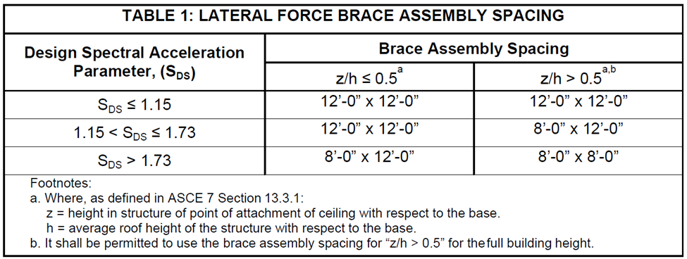
- There shall be a brace assembly at not more than ½ of the spacing required by Table 1 from each surrounding wall, expansion joint, and ceiling edge at any vertical offset. For example, where the brace spacing is 8’ x 12’, the edge distance shall be 4’ in the direction of the 8’ spacing and 6’ in the direction of the 12’ spacing.
- The slope of bracing wires shall be ≤ 45° from the horizontal plane and wires shall be taut. Splices in bracing wires shall develop the wire’s allowable load. Only 1 splice is permitted in the entire length of a single brace wire.
- Compression struts shall meet the following requirements:
- The strut shall be sized to adequately resist the vertical component force induced by the ceiling bracing wires and have a max kl/r ≤ 300.
- The strut shall be ≤ 1 (horizontal) in 6 (vertical) out of plumb.
- Separate compression struts ≥ 6” from all unbraced ducts, pipes, conduits, etc.
- Changes in the ceiling plane elevation shall have independent positive bracing systems for lateral movement and seismic loads.
Attachment of Hanger and Bracing Wires
- Fasten hanger wires with ≥ 3 tight turns in 3”. Hanger wire loops shall be tightly wrapped and sharply bent to prevent vertical movement or rotation of the member within the loops.
- Fasten bracing wires with ≥ 4 tight turns in 1 ½”. Bracing wire loops shall be tightly wrapped and sharply bent to prevent vertical movement or rotation of the member within the loops.
- Hanger and bracing wire anchorage to the structure shall be installed in such a manner that the direction of the anchorage aligns closely with the direction of the wire.
- Separate all ceiling hangers and bracing wires > 6” from all unbraced ducts, pipes, conduits, etc.
- Hanger and bracing wires shall not attach to or bend around obstructions including but not limited to piping, ductwork, conduit, and equipment.
- Provide additional hangers, struts, and brace assemblies as required at all ceiling breaks, soffits, or discontinuous areas.
- Hanger wires that are > 1 (horizontal) in 6 (vertical) out of plumb shall have counter-sloping wires.
- Hanger wire connection to the structure above shall be capable of carrying ≥ 90 lbs. allowable load.
- Attachment of the bracing wires to the structure above and to the main runners shall be adequate for the load imposed.
- Power-actuated fasteners in concrete are not permitted for bracing wires.
- The DSA-approved construction documents shall include a plan for installing post-installed anchors in prestressed concrete when applicable. The plan shall demonstrate how the location of existing prestressing tendons and strands will be field-verified and denoted as necessary to avoid interference.
Expansion Joint and Seismic Separation Joints
- Expansion joints shall be provided in the ceiling at intersections of corridors and at junctions of corridors and lobbies or other similar areas.
- For ceiling areas > 2,500 sq ft, a seismic separation joint shall be provided to divide the ceiling into areas ≤ 2,500 sq ft.
Luminaires, Services, and Other Devices
- All luminaires, services, and other devices shall be mounted in a manner that will not compromise ceiling performance.
- Ceiling panels shall not support any luminaires, services, or other devices.
- Penetrations through the ceiling for sprinkler heads and other similar devices that are not integrally tied to the ceiling system in the lateral direction shall comply with 1 of the following:
- Provide a 2” oversized ring, sleeve, or adapter through the ceiling tile to allow free movement of 1” in all horizontal directions.
- Provide a flexible sprinkler hose fitting that can accommodate 1” of ceiling movement.
- Slack safety wires shall be considered hanger wires for installation and testing requirements.
- With independent vertical support, the system, including attachment to the structure above, shall be capable of supporting 4 times the weight of the luminaire or service – additional slack safety wires are not required.
Luminaires
- All luminaires shall be positively attached to the ceiling suspension systems by mechanical means. A min of 2 screws or approved fasteners capable of resisting a horizontal force equal to the weight of the fixture is required at each light fixture.
- Surface-mounted luminaires shall be attached to the main runner with at least 2 positive clamping devices on each fixture. The clamping device shall surround the supporting ceiling runner and be made of steel with a min thickness of 14-Ga. Rotational spring catches do not comply. A 12-Ga slack safety wire shall be connected from each clamping device to the structure above. Provide additional supports when luminaires measure 8’ or longer or exceed 56 lbs. Max spacing between supports shall be ≤ 8’.
- Luminaires weighing ≤ 10 lbs. may be supported directly on the ceiling runners, but they shall have a min of 1, 12-Ga slack safety wire connected from the luminaire housing to the structure above.
- Luminaires weighing > 10 pounds but ≤ 56 lbs. may be supported directly on the ceiling runners, but they shall have a minimum of 2, 12-Ga slack safety wires connected from the luminaire housing at diagonal corners to the structure above.
Exception: All luminaires > 2’ x 4’ and ≤ 8’ long weighing < 56 lbs. shall have a 12-Ga slack safety wire at each corner. - All luminaires weighing > 56 lbs. shall be independently supported by ≥ 4 taut 12-Ga hanger wires (1 at each corner) attached from the luminaire housing to the structure above or other approved hangers.
- Where pendant luminaires are to be installed in areas with a suspended ceiling, the construction documents shall include complete support details.
Services within the Ceiling
- All flexible sprinkler hose fitting mounting brackets, ceiling-mounted air terminals, solar daylight tubes, or other services shall be positively attached to the ceiling suspension systems by mechanical means to resist a horizontal force equal to the weight of the component. Screws or approved fasteners are required. A min of 2 attachments are required at each component.
- Ceiling-mounted air terminals or other services weighing ≤ 20 lbs. shall have 1, 12-Ga slack safety wire attached from the terminal or service to the structure above.
- Flexible sprinkler hose fittings, ceiling-mounted air terminals or other services weighing > 20 lbs. but ≤ 56 lbs. shall have 2, 12-Ga slack safety wires (at diagonal corners) connected from the terminal or service to the structure above.
- Flexible sprinkler hose fittings, ceiling-mounted air terminals or other services weighing > 56 lbs. shall be independently supported directly from the structure above by ≥ 4 taut 12-Ga hanger wires attached from the terminal or service to the structure above or other approved hangers.
Other Devices within the Ceiling
- Miscellaneous lightweight devices weighing ≤ 20, such as strobe lights, occupancy sensors, speakers, exit signs, etc., shall be attached to the ceiling grid. In addition, devices weighing > 10 lbs. shall have 1, 12-Ga slack safety wire anchored to the structure above.
Additional T-Bar Requirements
Fire-Resistance-Rated Ceilings
- Provide a detail and tested assembly number for fire-resistance-rated ceiling assemblies from an authorized testing agency. The components and installation details must conform in every respect with the listed detail and number. Details shall depict all components, including insulation materials, framing, and attachment of the design so that the assembly can be constructed and inspected accordingly.
- Pop rivets, screws, or other attachments are not acceptable unless specifically detailed in the listed construction detail(s), or an approved listing by a State Fire Marshal (SFM) recognized laboratory.
Acoustical Ceiling Tile Panel Clearance
- For ceiling installations utilizing acoustical tile panels of mineral or glass fiber, it is not mandatory to provide ¾” clearance between the acoustical tile panels and the wall on the sides of the ceiling which are free to slip.
Other Panel Types
- Panels weighing > ½ PSF, other than mineral fiber and glass fiber acoustical tile, and all metal and wood panels shall be positively attached to the ceiling suspension runners by mechanical means, such as bolts, cables, carabiners, d-shaped rings, screws, or rivets, and each attachment shall have the allowable design strength to support 100% of the weight of the panel acting in any direction. A min of 2 attachments are required for each panel. For ceiling installations utilizing panels other than mineral or glass fiber, ¾” clearance shall be provided between the ceiling panel and the wall on the sides of the ceiling area which are free to slip, unless otherwise justified by seismic qualification indicated below.
- The use of other types of attachment, such as clips, snap-in devices, perforated lips, clamping devices or spring-loaded devices or hooks, shall be listed per IR A-5 and identified for use with the type of ceiling framing members and panels.
- An alternate means of compliance per the California Administrative Code may be proposed and reviewed on a project-by-project basis when using unlisted means of attachment. The alternate means of attachment shall have the allowable design strength to support 100% of the weight of the panel acting in any direction and shall be capable of maintaining that strength if the ceiling grid is distorted or out of level.
- In lieu of direct restraint attachments, it is also permitted to provide a secondary means of connecting the panel to the grid or structure to retain the panel in case of panel dropout, ceiling grid distortion, and ceiling grid becoming out-of-level. The secondary attachment shall have the allowable design strength to support 2 times the weight of the panel acting in any direction, such as a slack wire or cable.
- Special attachment details complying with one of the methods outlined above, such as screws or cables, shall be provided at the perimeter of the ceiling, where panels are cut or altered, and where non-standard panel sizes or edge conditions occur.
Exits
- Ceilings over exit paths shall be installed per ASCE. A main or cross runner shall be installed on all sides of each piece of tile, board, or panel and each luminaire or grill. Splices or intersections of such runners shall be attached with through connectors such as pop rivets, screws, pins, plates with end tabs, or other approved connectors.
Free-Floating Ceilings
- Free-floating ceilings (ceilings not attached to any walls) supported by wires per this IR shall be braced per above, regardless of the ceiling area, unless it can be demonstrated the anticipated ceiling movement will not cause failure of the ceiling components or failure of mechanical, electrical, plumbing, or fire and life safety components/systems within the ceiling area and the area of anticipated movement. The anticipated movement can be assumed as the hanger supports swinging to a 45° angle from vertical in any plan direction.
- The perimeter of free-floating ceilings shall be supported by a continuous runner.
Sloped Ceilings
- Sloped ceilings with acoustical, mineral, or glass fiber tiles, surrounded on all sides by partition walls are permitted per the requirements of this section. Sloped ceilings not meeting the requirements of this section shall be custom-designed and detailed.
- The slope of the ceiling shall not exceed the manufacturer’s published max slope recommendation nor 25° from horizontal, whichever is <. The ceiling shall be square or rectangular in plan. The structure above the sloped ceiling may be flat or sloped in a different direction.
- The slope shall occur across a single plane. The slope of the ceiling is to be uniform from the intersection of the wall at the lowest end of the ceiling to the intersection of the wall at the uppermost end of the ceiling. A gable or multifaceted ceiling profile can be accomplished within the parameters of these provisions by replacing a full-height wall with a soffit at the ridge or each slope transition line. The design must demonstrate the soffit construction provides strength and stiffness in the plane of the ceiling equivalent to a full-height wall.
- Sloped ceilings shall comply with the following detailing requirements:
- The attachment of proprietary perimeter clips to the walls shall comply with this code.
- Main runners are to be installed parallel (up/down) to the direction of the ceiling slope.
- Runners at the bottom/lower end of the slope shall be installed as the attached side.
- Runners at the top/higher end of the slope shall be installed as the free side.
- Perimeter wall angles at the top and bottom of the slope are to be shimmed or installed with adjustable wall mounting brackets such that the bottom leg of the angle aligns with the plane of the ceiling. This is to ensure the 90° angle of the wall trim in relation to the runner is maintained. Bending the leg(s) of the wall trim to match the slope of the ceiling is prohibited.
- Hanger wires, including slack wires, are to be installed vertically and plumb.
- Compression struts are to be installed vertically and plumb.
- Brace wires are to be installed at a maximum of 45° from the horizontal plane.
- Shims between the tiles and the grid are required to ensure panels are centered to resist sliding out.
- Panel edge hold-down clips are to be installed along the top of the grid to the ceiling tiles as follows:
- For ceiling slope ≤15° from horizontal: Clips are to be installed at each main runner and cross runner around the perimeter of the ceiling in the first bay adjacent to the walls.
- For ceiling slope > 15° but ≤ 25° from horizontal.
- Maintain min ¾” clearance of the runners to the wall angle at the free sides.
- Seismic clips to attach 7/8” wall angle to the ceiling grid is required. The seismic clip shall be attached to the wall angle with 2 screws.
- Sloped free-floating ceilings are beyond the scope of this IR. The design professional is responsible for providing project-specific design (including supporting calculations) and details.
Electrical
- All work done in a neat, workmanlike manner CEC 112.12
- Emergency lighting – battery test on final
- Illuminated directional emergency exit lighting (path of travel) (avg 1 ft candle) CEC 1008.3.5
- Rough electrical (open boxes for inspection)
- Junction boxes accessible and working clearances
- Conductor staples: every 4.5’ and 12” from the box CEC 334.30
- FMC secured within 12″ and every 4.5′
- EMT secured within 3′ of the box and every 10′
- Abandoned cables cannot remain
- Cables and raceways cannot be supported by the grid – marking of wires supporting electrical CEC 300.11.A.2
HVAC
- Design, construction, and workmanship shall comply with accepted engineering practices and shall be of such character as to secure the results sought to be obtained by this code.
- HVAC ducting off-grid and lighting
- HVAC ducting insulated (un-conditioned space)
- Working space for HVAC disconnect switches 30″ wide
Air Terminals
- Air terminals weighing < 20 lbs. shall be positively attached using sheet metal screws. ≥ 2 screws installed on each side of the terminal, near corners, and fastened into main runners
- Air terminals 20-56 lbs., In addition to the above, shall have 2, 12-Ga hangers connected from the terminal or service to ceiling system hangers or the structure above. These wires may be installed with limited slack
- Air terminals > 56 lbs. supported directly from the structure above by approved hangers
Return Air Plenums
- Verify materials meet flame spread rating for return air plenums and ducts (plenum rated)
- Equipment and devices shall be permitted only when necessary for direct action upon, or sensing of the contained air
- The fire-damper is clear and operational
- Communication plenum-rated cable (CMP) is listed as suitable for use in ducts, and plenums and listed as having adequate fire resistance and low smoke-producing characteristics
Misc Ducting
- Hood ducting (certified welder cert – light inspection)
- Hood makeup air
- Dryer ducting
- Dryer makeup air
Insulation
- Insulation – flame spread index < 25 and smoke-developed index < 450
- Paper-faced insulation is not permitted in exposed above-ceiling areas, open side of furred spaces, and ventilated interstitial spaces due to the potential of embers igniting paper